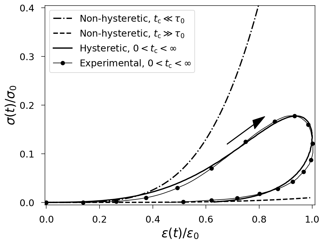
Fig. 1. Typical dynamic stress-strain curves and loops describing the felt material. The arrow indicates the direction of the material loading.
Felt is produced through a process called felting. In this process, fibers are intertwined through heat, moisture, and pressure, resulting in a randomly oriented structure. The structure allows felt to be used in several industries, such as automotive and aeronautical, because of its noise reduction, damping, and shock absorption properties. The governing equation describing wave propagation in felt is derived from the 1D equation of motion \[\rho\frac{ tial^2u}{ tial t^2}=\frac{ tial\sigma}{ tial x},\] where \(\rho\) is the density, \(u(x,t)\) is the displacement, and \(\sigma\) is the stress. The experimentally confirmed constitutive relation is the following: \[\sigma(\varepsilon)=E_{\rm d}\biggl[\varepsilon^p(t)-\frac{\gamma}{\tau_0} \int_0^t\varepsilon^p(\xi)\exp{ \biggl(\frac{\xi-t}{\tau_0}\biggr)}{\rm d}\xi\biggr],\] where \(E_{\rm d}\) is the dynamic Young’s modulus, \(\varepsilon = tial u / tial x\) is the strain, \(p\geq 1\), \(p \in {\rm I\!R}\) is the exponent introducing the nonlinearity, \(0\leq \gamma < 1\) is the hereditary amplitude, and \(\tau_0\) is the relaxation time [1, 2, 3, 4].
To understand the felt material, it is essential to understand the hysteresis loop dynamics in the force-compression tests. Examples of the measured and fitted stress-strain curves are shown in Fig. 1. It can be seen that in the general case for \(0 < t_{\rm c}<\infty\), the loading and unloading branches do not follow the same path. The hysteresis loop means that felt is a material with memory. Analysis of (2) shows that under a rapid material loading-unloading cycle lasting for \(t=t_{\rm c}\ll\tau_0\), and for a slow loading-unloading cycle \(t=t_{\rm c}\gg\tau_0\) constitutive equation (2) takes the following forms, respectively: \[\sigma(\varepsilon)=E_{\rm d}\varepsilon^{p}(t), \qquad\sigma(\varepsilon) = E_{\rm s} \varepsilon^{p}(t),\] where \(E_{\rm s}=E_{\rm d}(1-\gamma)\) is the static Young’s modulus. The material loading and unloading curves for these limiting cases (3) follow the same path in both loading directions, as shown in Fig. 1.
A dispersion analysis conducted on model (1) reveals the existence of a band gap (BG) and a negative group velocity (NGV). Both properties are surprising for a material that is composed of randomly oriented elastic fibers. It can be shown that for realistic parameter values the BG and NGV influence only low-frequency wave components. For valid parameter values, there are no dispersive effects driven by NGV [4]. The presented model sheds light on the acoustics of fibrous and porous materials in general. This work was supported by the Estonian Research Council (PRG1227).
[1] Yu. N. Rabotnov, Elements of Hereditary Solid Mechanics, MIR Publishers, Moscow, USSR, 1980.
[2] A. Stulov, “Experimental and computational studies of piano hammers,” Acta Acust united Ac, 91(6), (2005), pp. 1086–1097.
[3] D. Kartofelev, A. Stulov, “Propagation of deformation waves in wool felt,” Acta Mech., 225, (2014), pp. 3103– 3113.
[4] D. Kartofelev, A. Stulov, “Wave propagation and dispersion in microstructured wool felt,” Wave Motion 57, (2015), pp. 23–33.