
In the modern rapidly changing world new more and more environmentally friendly ways of producing electricity are gradually emerging, people are beginning to economise electricity. For this reason smart supply unit was designed in order to reduce consumption of electricity. It consists of a power regulator and a meter for measuring amount of energy consumed.
Model of Smart supply unit and a power regulator was designed as circuit diagram.
In the first block alternating current (~220V) falls into current transformer where during flowing along the winding of transformer induces current in the secondary winding (it consists of 1000 turns). Current of secondary winding will be used for equipment which is connected to smart unit supply designed to measure amount of energy consumed.
In the second block voltage transformer of one primal and two secondary windings is used for supplying control circuits of smart supply unit and for measuring voltage.
In the third and fourth parts of smart supply unit power regulator is shown. Opto-isolator (OK2) which is situated in the third part is used for discovering the point '0' of crossing. The forth part is used for controling level of average voltage of equipment connected to smart supply unit (with aid of Triac (T2)). Such circuits are appropriate to use when control is performed digitally. Control is performed by the programme of modulation of wave length which is situated in Atmega32 microcontroller and connected to the circuit SV2 with link.
Values of current and voltage are measured using analogical digital converter of microcontroller. After processing the values of current and voltage the values of instantaneous voltage and current are obtained, values of RMS (root-mean-square) are calculated real, apparent and reactive powers and power factor as well.
In order to control transmitted power the controling element semiconductor of alternate current is chosen, Triac (T2).This element is being opened after transfering an impulse to the controling terminal in certain time when a sinusoid is crossing the point '0'. When Triac (T2) opens it transmits the current until the sinusoid of value again crosses the point '0'.
Below the formula Eq.(1) is given where output voltage of power regulator is calculated:
$$V_{\text{out}} = \frac{T_{\text{DC}}}{T_{\text{total}}} \cdot V_{\text{in}} \tag{1}$$where Ttotal = 1/50s, Vin - input voltage, TDC – duty cycle
The graph Fig.1 given below shows that average voltage while outgoing fluctuates proportionally the delay of opening Triac (T2)
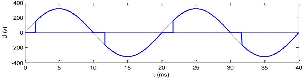
So such method of control is characterised by spreading large amount of harmonics into network, also by the factor of little power. For this reason decent filtration is necessary.