
SuperNEMO (NEMO stands for Neutrino Ettore Majorana Observatory) experiment is devoted to search for the neutrinoless double beta decay - a rare, lepton-number violating, nuclear decay process that would indicate the Majorana nature of neutrinos, as well as provide an estimate for the neutrino mass scale.
The experiment is currently being built; it will consist of identical 20 modules, each housing 7 kg of source (82Se is the baseline choice). The module will consist of thin source foils, placed inside a tracking system, all surrounded by a calorimeter (Fig. 1). This gives the ability to measure individual electron tracks, vertices, energies and time of flight,
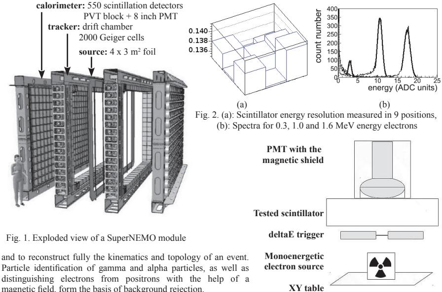
and to reconstruct fully the kinematics and topology of an event. Particle identification of gamma and alpha particles, as well as distinguishing electrons from positrons with the help of a magnetic field, form the basis of background rejection.
SuperNEMO aims to achieve the calorimeter energy resolution to 7%/$\sqrt{E}$ (MeV) at full width of half maximum (FWHM). To reach this goal, a large quantity of scintillators will have to be tested before installing. The setup for such tests was developed and built in Prague based on the experience of the collaborators in Bordeaux and Dubna. The setup consists of (i) the steel lightproof black box, with dimensions $100 \times 130 \times 130$ cm3, (ii) movable table in X and Y directions, (iii) so-called deltaE trigger, (iv) source of monochromatic energy electrons, where the electrons from 90Sr spectrum with the particular energy (Fig. 2b) may be chosen by applying a magnetic field with variable strength, produced by a coil. All electronic devices are connected with the computer and various settings can be performed by using the custom-built software in Linux operating system.
The setup itself is shown in the Fig. 3. The photomultiplier tube (PMT) is glued with the optical contact to the scintillator. Below the scintillator there is a deltaE trigger, consisting of two 14 mm diameter PMTs coupled to the 100 μm scintillator foil, and the electron source placed on the XY table. The table moves the electron source and the deltaE trigger to the desired position under the scintillator. Electrons with chosen energy cross the trigger and enter the tested scintillator, depositing their energy which is converted to electric signals and measured. The observable is the energy resolution, depending on the homogenity of the scintillating material as well as on the electron entrance place.
The routine tests of the scintillator detectors started May 2012 and is still ongoing with some breaks for hardware upgrade. The talk discusses various aspects of the setup functionality, data acquisition and technical challenges and solutions.