
For the last century, microwave usage has become more and more relevant. Microwaves are not only used in narrow fields like military radars or scientific cosmic background detectors but also they are seen in our everyday lives, for example, mobile phones, wireless network routers and microwave ovens. And, as usual, everything has its darker side. The more electronics develop, the more vulnerable they become to various electromagnetic attacks, such as, electromagnetic pulse (EMP) and microwave radiation [1]. Therefore, now we have another form of terrorism, which doesn't require a person to be near electronic devices or even in the same building in order to interrupt their work or irreversibly damage them. This is accomplished by using portable high power microwave generators and directional antennas [2]. That being the case, there are several projects in Europe which purpose is to find out countermeasures for such electromagnetic attacks [3]. My purpose of this work is investigation of the weakest part of every building – window. I will show and explain the results of four measured glasses which are used in modern window panes.
In my research I measured four aforementioned glasses in semi anechoic chamber, shown in Fig. 1 (a), while following far field conditions [4]. Investigation of transmission was done by calculating shield effectiveness (SE) parameter, which shows objects ability to shield from electromagnetic waves. SE is defined as ratio between power of incident signal and power of propagated signal through the object. SE is measured in dB and you can see its formula below in Eq. (1):
$$SE = 10 * \log \left( \frac{P_{inc}}{P_{glass}} \right) \tag{1}$$It is required to do logarithmic expression to calculate in dB. These units are easier to use than just the ratio itself because ratio may differ in several orders.
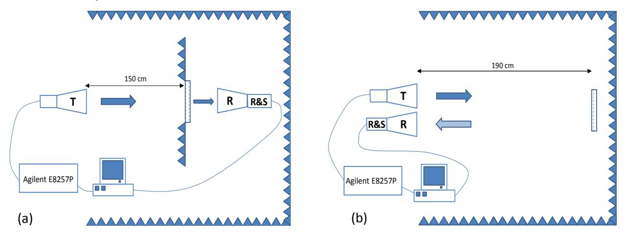
Second part of my research is measurements of reflectivity. They are done in the same conditions as transmission measurements, only antennas and sample layout differs, as you can see in Fig. 1 (b). Both antennas are parallel to each other and perpendicular to the sample in order to get almost 0 degree angle of incidence. Reflectivity (R) is a ratio between reflected power from the glass and reflected power from the metal plate. In this case reflectivity has values between 0 and 1. And the formula is shown in Eq. (2):
$$R = \frac{P_{from \ glass}}{P_{from \ metal}} \tag{2}$$