
The report contains discussions of the results of tests on sliding friction of a metal-polymeric friction pair by the accelerated multistage loading method. The experiment was carried out at the testing center SZ-01 (the developer is Scientific and Production Group TRIBOFATIGUE Ltd) according to the scheme (Fig. 1).
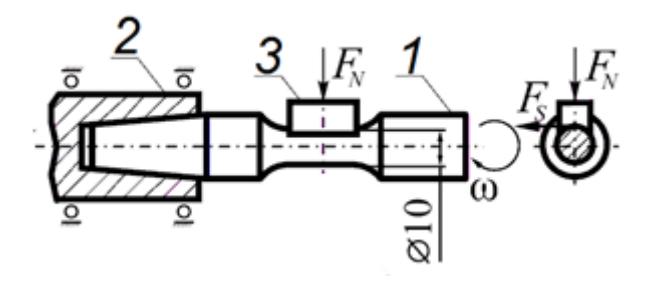
The cylindrical sample 1, made of steel 30, is fixed in the spindle 2 and rotates at angular velocity $\omega$. Being fixed immovably in the cassette, the control sample 3 (partial insert) with dimensions 10 × 10 × 10 mm made of Poly(methyl methacrylate) is pressed under the action of the contact load $F_N$ to its working area with the diameter $d$ = 10 mm.
In accordance with the proposed method, a step-by-step increase of the contact load $F_N$ is performed during the complete test time. To implement the program, the following are set: the criterion for reaching the limiting state ($k_i$ = const); initial level of contact load $F_{N0}$; duration ($n_i$ = const) of the loading stage; interval $\Delta F_{Ni}$ = const for increment of the contact load. The initial parameters are set depending on the assigned task; the number of cycles ($n_k$) at the last stage of loading is determined by the achievement of the limiting state; the transition from stage to stage is carried out without intermediate pauses; the tests are carried out continuously until the onset of the limiting state. In the described experiment, the initial contact load was $F_{N0}$ = 4 N, the increment step of the load $\Delta F_{Ni}$ = 2 N, the duration of the test stage $n_i$ = 9000 cycles. Figure 2 shows the loading program and kinetics of the friction force $F_s$ and linear wear $L$ change of the polymeric insert.
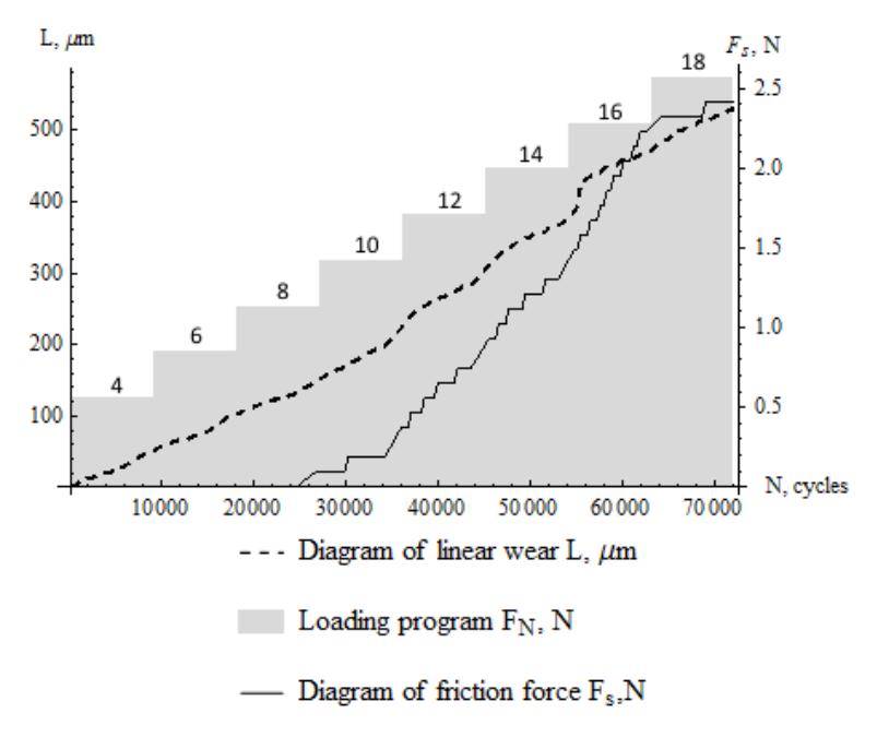
From the diagram (see Fig. 2) it is seen that the friction force is subject to oscillations even during one stage of loading; this process is non-stationary, as well as the value of linear wear.