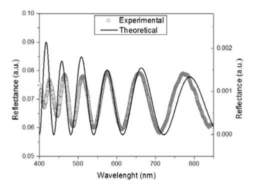
Various applications of thins film deposition methods requires non-destructive film thickness monitoring techniques. In holographic lithography experiments with negative tone photoresist materials thickness of the cross linked polymer depends on exposure conditions and developing recipes. In the current work photoresist samples exposed with 371 nm wavelength laser employing Lloyd's mirror holographic lithography system were investigated. Residual thickness of the samples exposed with different period interference fringes were investigated employing angular polarized white light reflectance measurements. Reflectance spectra were recorded using spectrometers AvaSpec-2048 (Avantes) spectrometer covering 350-780 nm spectral ranges with 1.2 nm resolution. Measurements were performed for two polarizations (TE (s), TM (p)) and different angles of incidence varied from 20° to 50°. Reflectance spectra were calculated normalizing reflected light to the lamp spectrum and subtracting noise (dark spectra obtained when the lamp was off). Characteristic interference fringes in reflectance spectra were explained by using Fresnel's expression for system consisting of three different refractive index medium [1]:
$$R = \frac{r_{12}^2 + r_{23}^2 + 2 * r_{12} * r_{23} * \cos(\delta)}{1 + r_{12}^2 \cdot r_{23}^2 + 2 * r_{12} * r_{23} * \cos(\delta)}\tag{1}$$$$\delta = \frac{2 * \pi}{\lambda} 2 * n_2 * d * \cos(\theta_t)\tag{2}$$where R- reflectance, $r_{12,23}$ – the reflection coefficient at the boundaries between mediums 1-2 and mediums 2-3, $\lambda$ – wavelength, n – refractive index, d – photoresist thickness, $\theta_t$ – angle which is found using Snell's law.
Experimental reflectance spectra (see Fig. 1) were explained varying photoresist thickness and calculating theoretical reflectance spectra with eqs. (1), (2) employing know photoresist [2] and glass substrate [3] refractive indices. Angles of refracted light were calculated employing Snell's law.