To use the favorable magnetic field sensing properties of nitrogen-vacancy (NV) centers in diamond the ground state electronic spin energy levels need to be manipulated (with a green laser and electromagnetic radiation in the microwave frequency range), which can be done by using the method of optically detected magnetic resonance (ODMR) [1]. To increase the efficiency of microwave delivery to NV centers in a diamond, a microwave antenna that is capable of creating a region with a uniform magnetic flux density distribution, generating microwaves with a specific polarization, that has a resonant frequency of about 2.87 GHz and also has a wide enough bandwidth for effective operation in dual-resonance magnetometry [2] can be used.
Previously, in most cases, this task was achieved by using a simple coil or wire antenna that could reach varying degrees of efficiency. In recent years, however, there has been an increasing number of studies with more "intelligent" types of antennas for applications in NV center experiments. Using a method from one such study [3] we are designing a new antenna, shown in Fig. 1a, for use in NV center based magnetometry experiments.
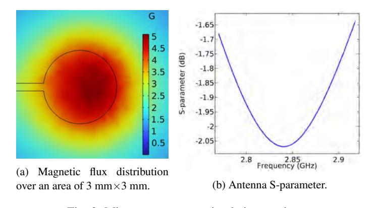
In this work, we are using COMSOL multiphysics software to model antenna prototypes and examine the relationships between the geometrical parameters (see Fig. 1b) of the antenna and its electromagnetic properties such as resonant frequency and bandwidth which are seen in expressions (1) and (2) respectively [3]. This knowledge will be essential for creating a new antenna design that meets the desired specifications for microwave polarization, frequency bandwidth and efficiency (see Fig. 2).
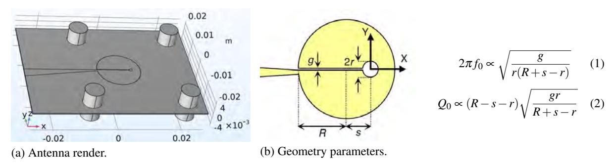
$$2\pi f_0 = \frac{g}{r}\sqrt{r(R+s-r)}\tag{1}$$
$$Q_0 = \frac{g r}{(R-s-r)}\sqrt{\frac{R}{s-r}}\tag{2}$$