For measuring of magnetic properties of different materials in a wide range of temperatures (20 – 300 K) and magnetic fields (up to 5 T), the controllable cryostat and magnetic field generator are needed. It was shown in Ref. [1], that for investigation of magnetic and electric properties of thin manganite films a closed cycle helium gas cryocooler (temperature range 20 – 300 K) and an electromagnet with a maximum amplitude of 0.8 T were used. For high-field magnetoresistance investigations the compact pulsed magnetic field generator (B up to 25 T, pulse duration 1 ms) based on capacitor bank discharge through the coil was designed [2]. However, the temperature in this generator could be changed only in the range of 80-300 K. Therefore, the design of pulsed magnetic field generator combined with the closed cycle helium gas cryocooler is an actual task. Moreover, the duration of magnetic pulse should be sufficiently long to avoid the transition processes and to measure the low-field magnetoresistance effects which take place in magnetic field range 0 – 100 mT.
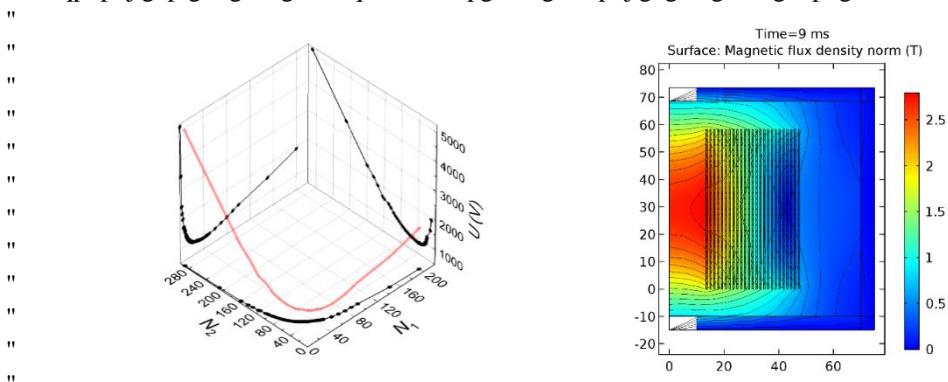
The main task of this work is to find optimal structure of magnetic coil for generation of a long ~100 ms pulse with amplitudes up to 5 T using a 5.4 mF capacitor charged to 2 000 V, and to investigate how magnetic field depends on the structure of this coil. A special rectangular-shaped wire 1.75×0.5 mm was chosen. To simulate the coil parameters the COMSOL Multiphysics program was used. The first step was to find optimal structure of the coil. During simulations it was found, that increasing the number of windings more than 30, or number of layers more than 13, does not significantly increase the magnitude of the magnetic field. Considering this, the optimal relation between number of windings N1 and number of layers N2 was found: 2:1. Fig. 1 presents simulation data plotted in a 3D graph. The left graph shows almost all possible coil structures that fit our needs. For optimal scenario, the smallest possible voltage was used. The figure on the right presents magnetic flux density distribution of the coil model consisting of 30 windings and 50 layers, when capacitor was charged up to 970 V. In this case the maximum B=2.7 T in the center of the coil was achieved. The real coil was constructed with N2:N1= 46:23 and tested with the cryocooler. It was found that the magnetic field of 5 T could be achieved with a little higher voltage than simulated (1900 V). The pulse length was shorter as predicted: 60 ms. After testing the coil with a manganite sample placed in the cryostat, we found that the pulse amplitude and duration fully satisfies requirements for the magnetoresistance investigation in the intermediate (up to 5 T) magnetic fields in the temperature range (20-300) K.